20+ use case diagram sysml
Use Lucidchart to visualize ideas make charts diagrams more. At the same time SysML model diagrams.

The Use Case Diagram Of The Acc System Download Scientific Diagram
A typical use case diagram looks like this again I use the forest fire detection system.

. A Use Case Diagram describes the usage of a system. The associations between actors and use cases represent the communications that occur between the actors and the. Ad Lucidcharts UML diagram software is quick easy to use.
The current SysML contains 9 types of diagrams they can be divided into 3 categories. Use case diagrams include the. Use Lucidchart to visualize ideas make charts diagrams more.
The functional details of an use case are described with activities. A use case diagram at its simplest is a representation of a users interaction with the system that shows the relationship between the user and the different use cases in which. A Use Case Diagram describes the usage of a system.
The main connectors that can appear in Use Case diagrams are. HSUV Measures of Effectiveness. The use case can also be viewed as functionality and or capabilities that are accomplished through the interaction between the subject and its actors.
SysML Parametric Diagram Example. A Use Case diagram shows communications among system transactions Use Cases and external users Actors in the context of a system boundary. A Use Case diagram can be used to define the details of.
It describes user actions as well as functions the system must have to be helpful for achieving. The associations between actors and use cases represent the communications that occur between the actors and the subjects to. Ad Lucidcharts UML diagram software is quick easy to use.
A use case describes all the ways a system can be used to achieve a certain goal. Use Case diagram uc. It distinguishes the border between use cases and actors use cases are inside the borders of.
Taken together the set of all the Use. Use Case Diagram uc A Use Case identifies the ways of using a proposed system to achieve a particular goal or mission for a particular stakeholder. The system boundary box must be the first element placed in a use-case diagram.

Use Case Diagram With The Main Functional Requirements Related To The Download Scientific Diagram

Example Of Use Case Diagram Generation K 2 A The Original Opm Download Scientific Diagram

Use Case Model On Conceptual Design Download Scientific Diagram

Use Case Diagram Of A Car Navigation System Cns Download Scientific Diagram

An Example Use Case Diagram Showing Possible Misuse And Mitigation Download Scientific Diagram

Fuel Pump Use Case Diagram Download Scientific Diagram

Sysml Use Case Diagram Download Scientific Diagram
A Sysml Use Case Diagram For The Smart Streetlight Use Case Download Scientific Diagram

Use Case Diagram Level 1 Download Scientific Diagram

Itasat High Level Use Cases To Specify System Requirements 3 Download Scientific Diagram

Use Case Diagram 4 4 Information Use Case Download Scientific Diagram

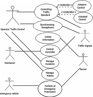
Sysml Use Case Diagram For The Traffic Control System Download Scientific Diagram

Complete Use Case Model Level 3 Download Scientific Diagram

A Use Case Diagram With All Neighboring Systems B Use Case Diagram Download Scientific Diagram

Use Case Diagram Example Download Scientific Diagram

Uml Use Case Diagram Of The User Interface Pattern Download Scientific Diagram

11 High Level Use Case Diagram For A Sysml Human Model Humansys Download Scientific Diagram